|
Internal 2 Lines
|
Internal connection (AP03).
|
|
Internal 4 Lines
|
Internal connection (AP02 and AP04).
|
|
Optima OPT-CD7
|
USB connection. (Pole Display)
|
|
Internal Screen
|
Internal connection (AP05*, AP06).
|
|
External Ethernet
|
Ethernet connection, IP and Port required.
|
|
External Screen
|
USB connection.
|
* When GoPOS is in register mode, the AP05 internal 10" customer display is split into two sections. One section is used to display the current transaction and the other section is used to display advertisements. To use the advertisement feature, you need to copy the images you want to display in the AP05 slide show folder.
ØCreate your advertisement image (bmp, gif, tif, png, jpg, etc) with recommended size of 512x600. Different sizes will work but may not display properly.
ØCopy the image or images to a USB thumb drive.
ØInsert the thumb Drive into USB port at back of AP05.
ØActivate Android Bars from GoPOS and open up Android File Manager.
ØNavigate to the thumb drive and select the image or images you wish to copy. Press in the check box to the left of the image to select one or more images. You may also select all files in the current folder by pressing on Select ALL in the Action menu.
ØNavigate to the AP05 slide show folder by pressing Home, Internal Memory, opos, slideshow. Press Action in the top menu and press Copy Selection Here to copy the file or files.
When you are in GoPOS Register Mode, the system will cycle through and display each image you copied into the AP05 slide show folder.
|
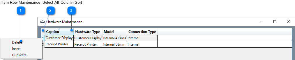
 Hardware Maintenance
.png)
-number-1.png)
-number-2.png)
.png)
.png)
.png)
.png)
-number-3.png)
.png)
.png)
-number-4.png)
-number-5.png)